Tuesday, July 21, 2015

No heater hum here...

Here is a pic of the guts of my 18-Watt Lite IIb build. Note that I did NOT twist the heater wires and they are NOT tucked neatly into the corner of the chassis. All I did was make sure they are as parallel as possible around other signal wires and most importantly all other wires cross them at 90-degree angles and don't touch them.

This amp has ZERO heater hum...


Google pictures of Soldano amps. They take it to the extreme... the wires are run parallel but they are also about 1" apart.

Discuss if you like below....

Tuesday, June 23, 2015

More Oscilloscope Tests.... now on my Simple20

Hey Merlin, if you are reading this I have real screen caps from my Rigol this time ;-)

I decided I wanted to see what the waveforms look like for my scratch-built Simple20 guitar amp. I made this amp in the Summer of 2014. (You can see a description of the Simple20 guitar amplifier at the end of this post.)

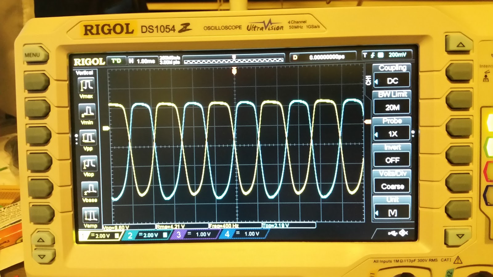
I used a function generator app on my Android phone to get me a 400Hz signal at about 80mVp-p for testing. As you can see, I got a nice and clean sine wave from that setup.
Here is the color-key for these traces in the screen caps...

Yellow: input signal from phone (50 mV/div)
Light Blue: post 1st gain stage coupling capacitor (50 mV/div)
Pink: post 2nd gain stage coupling capacitor (input to master volume control) (5 V/div)
Dark Blue: post phase inverter (one side of long-tailed-pair) coupling capacitor (50 V/div)
Note that the volts-per-division settings are different for each trace

This first picture is with the preamp volume  at 100% and the master volume at 0%. As you can see, each gain stage keeps the signal nice and clean... no clipping or distortion of the wave is evident at all. I do notice that not everything is exactly 180-degrees out of phase. I'm not sure why that is the case. I want to investigate that further. I also would have expected the Lt Blue trace to be more than only about twice the peak-to-peak voltage of the input signal. As you can see the voltage then jumps way up to 21.6 Vp-p after the second gain stage with the volume on full-blast.
Preamp Volume @ 100%, Master Volume @ 0%

Now with the other settings equal, I started to turn up the master volume. Here the MV is at about 75%. Looks pretty clean on the phase-inverter output. However, from real-world experience with this amp, things are really crunchy at this point so all that crunch must be from the power tubes at this setting. Notice the phase inverter is sending about 52 Vp-p to its power tube.
Preamp Volume @ 100%, Master Volume @ 75%

Here the master volume is at 100%. Notice now we are driving the phase-inverter into pretty heavy clipping on the peaks of the wave. The troughs are still pretty smooth but they are starting to noticeably flatten. From real-world experience this is pretty heavily distorted to the point where I don't particularly care for the sound. It's not blocking distortion or anything... just not pleasing to my ears is all. You can see the phase-inverter is putting out 104 Vp-p at this setting. It is contributing quite a bit to the distortion of the amp and at that voltage level, the power tubes are probably distorting like crazy too. My next experiments will involve breaking out my 100x probes and looking at the waveforms coming out of the power tubes at these same settings.
Preamp Volume @ 100%, Master Volume @ 100%

Background Information on the Simple20...
The Simple20 is a mating of the AX84.com "Core Projects" Simple Preamp and  20-Watt Push-Pull Power Amp that uses a long-tailed-pair phase-inverter and 6V6 power tubes. The amp was originally designed for use with 12AX7 preamp tubes. I currently roll JAN Phillips 12AT7 tubes for both the preamp and the phase-inverter and JJ 6V6 power tubes. I added a one-tube reverb circuit to the amp and I run it all into a 12" Warehouse Guitar Speakers (WGS) ET65. I used Edcor power and output transformers. This amp sounds absolutely AMAZING. When that WGS speaker got broken-in this thing just came alive. I get A LOT of comments from people on how nice it sounds - quite often from other guitar players who wonder what the heck it is. I mostly use it with my PRS Single Cut with their #7 pickups. This is the amp and guitar I use live for the band I play in: the Sonhouse Blues Band. It has an amazing clean tone, a fantastic edge-of-overdrive tone which I can dial in directly or it is also easy to switch-in with a nice clean boost pedal. It can get nicely nasty when pushed hard and with the right pedals this amp will do anything very very well. For a clean boost, I currently use the EH Soul Food pedal.

This is a picture of the inside of my Simple20 and how I hooked-up the probes for these screen caps:
Probing the Simple20

The second tube socket from the right is unused. There are some components on some terminal strips at that socket but they are currently not connected to anything. I was experimenting with adding a third gain stage. I really liked the results but I needed to go back to the original topology for my next gig. It was a great learning experience though! The third tube socket from the right is the reverb tube. All of the reverb components are on the terminal strips right there at the socket. The next tube is the phase-inverter and then the two power tubes. Looking at the rear panel of the chassis, at the top right you can see the dwell and reverb level control pot knobs, the reverb send and return jacks and the hole on the rear of the chassis where the reverb transformer wires enter and leave the chassis. The white chicken-head knob there is the speaker impedance selector switch.

The turret boards are as follows going left to right:  Power supply (horizontal components, solid-state rectifier.) Then comes the power amplifier section, a gap, and then the blue board holds the preamp's components.

I absolutely LOVE this amp. I have to say though, if someone offered me $1000 for it, I'd sell it to them and build myself two more!!! One just like this one and one in a 50-watt 6L6 or KT77 version.

Thanks for looking and I would love to hear your comments below!

-Darren

Friday, June 19, 2015

My New Oscilloscope with my 18-Watt Lite Ib

I finally pulled the trigger and bought an oscilloscope. I was going to buy a PC-based USB scope but read some horror stories about people frying their laptops and PC's so I chickened-out and bought a desktop digital storage oscilloscope. I went with the very popular Rigol DS1054Z. I've been playing with it using some pretty low level stuff from a signal generator just to figure out how to acquire a signal and get it triggered properly.

Tonight I finally got up the nerve to hook it up to my 18-Watt Lite IIb tube guitar amp that I made. This is a very nice amplifier based on the Marshall 18-Watt amps of legend. These amps are known for having pretty much all of their overdrive from the phase inverter and the power amp. I did some tests and verified this does in fact seem to be the case. I fed it a 100mVp-p 400Hz sine wave, verified at the source that it was in fact a nice smooth sine wave at all volume settings with the preamp tube in parallel mode.

Next I hooked up two channels of my scope to the phase inverter, one channel on each side. This was a really good exercise for me because it really illustrate very cleanly exactly what the phase inverter does.

Here is a picture of the phase inverter output at a pretty low volume. Based on my actual experiences with the amp, this setting would be very clean albeit not anywhere near full volume level. Each side of the phase inverter is its own color so you can clearly see that the two signals are exactly 180 degrees out of phase. You can also see that the sine waves are nice and smooth... no real overdrive here to speak of, or if there is any it is extremely mild...
(Yes I know my scope has the capability to capture a screen-shot but I haven't played with that feature yet... sorry.)


This next picture is with the volume turned up to a nice medium "crunch" setting based on experience. You can see the tops of the waveforms are beginning to flatten-out - that is the phase inverter starting to "overdrive." Very cool to see it coming from my own amp...


This last picture is really cool and leads me to a couple of questions. It is of the amp turned up pretty high... not quite on eleven...
(I had to shift the vertical center up a bit to get it all on the screen as you may have noticed.)

First thing I notice is that not only are the peaks getting much flatter, but you can also see that the troughs of the sine waves are now getting deformed but in a different way than the peaks. This I need to research... I think I remember Merlin Blencowe writing about this in his awesome tube preamp design book... I will go check on that.

The other thing I notice is that the yellow trace does not extend down quite as far as the blue trace. This is somewhat noticeable in the second picture but here it kind of jumps out at me. Is this a result of the 12AX7's triodes being "unbalanced?"

Another interesting thing to note is that these are all traced with the tone knob all the way down. With it on any other setting, the traces got really jagged-looking. Wondering about that too.

Would love to hear your thoughts on this. You can comment below or join my oscilloscope thread on ax84.com's forum.


Friday, March 27, 2015

Idea for a clean preamp

EDIT April 2, 2015 9:38 AM
Updated version. Thanks for the feedback received so far!!!


ORIGINAL POST:
Would love any feedback on this idea I had...


Background:
I was reading through "The Ultimate Tone Volume 5" by Kevin O'Connor and was intrigued by some of his ideas for three-stage clean preamps. Build it up, tear it down, build it up, tear it down, build it up, tear it down. Each build-up adds harmonics, each stage has different values for anode and cathode resistors, the third stage is a different tube than the first two. Each stage should add it's own unique character to the tone.

I was also reading a thread about tonestacks on AX84.com and Merlin suggested a Bandmaster for treble and bass coupled with a Bridged-T for mids. So I threw those in there too to try out something different.

EDIT May25, 2015 8:40 PM
I ordered some of Merlin Blencowe's (The Valve Wizard) B9A Development Boards and decided they would make a great platform for prototyping this design. Here is how they turned out:


I really like how easy it is to do a layout and swap out components quickly and easily! I printed a full-sized image of the board on my laser-printer and penciled-in the components to plan my layouts and then made minor tweaks as I placed the components on the boards. In the top picture, the preamp's 12AU7 stages and Bandmaster tone stack are on the board on the right. The 12AX7 preamp's stage 3 and cathode follower with T-Bridge mid control and volume knob are on the left board. (You can click on the pictures to make them larger.)

I think these boards are very nicely thought-out and implemented. I love how you can solder either side so that changes can be made without ripping the boards out of your chassis. However, I feel that they are a little large (10 cm square) if your intention is to make these into a permanent install. For a simple one-channel amp like this, they would be just fine. But remember, you still have to fit your power supply and output tubes in there. If you are going to do a multi-channel amp with reverb and effects these are not very practical for permanent installation. However, I don't think that was the original design intent for these anyways. I think they were money VERY well spent for fast prototyping.

Those large 47uF/450V F&T filter caps will eventually be replaced by radial lead caps that will fit the boards a bit better. I just had those on-hand for testing. You can see I left the leads for them long on the bottom of the board so I can use them on another build someday.

Up next, wiring it into a power-amp... some time later this summer I hope! I am getting anxious to see how this will sound.